Friday, July 24, 2009
Export Autocad Linework to Google Earth
If you are curious as to what my stream surfaces look like, then you can download my recent tinn surface in kmz here:
http://sites.google.com/a/streamrestoration.info/civil3d/gis/STREAM.kmz?attredirects=0
You can download the Autodesk Labs Google Earth Extension here:
http://labs.autodesk.com/utilities/google_earth_extension_beta/
The command is "publishkml".
Sunday, May 24, 2009
Ton Ten Uses of an iPhone for Stream Restoration
-------------------
1. Tethering
Use your iphone to connect to the internet. This will enable Google Earth to get realtime terrain and images. With 5.0, you can see your gps position on Google Earth if you connect to a handheld unit (Garmin or Magellan). Use both the iPhone and GPS unit in conjunction to see your location on your laptop. If you export your sitework linework via kml (http://civil3d.streamrestoration.info/2009/07/export-autocad-linework-to-google-earth.html), then you can see yourself realtime in relation to your site.
(Jailbreaking is necessary)
-------------------

A simple video recorder that works well. (Jailbreaking is necessary)
--------------------
3. Note2Self
Make quick notes to yourself out in the field with this versatile voice recorder. It will also let you email the sound clip to anyone.
--------------------
4. Weatherbug Plus
See when huge storms are coming in on a realtime Doppler radar map so you know when to prepare.
--------------------
5. Tracks
Record your gps track while out in the field.
--------------------
6. Google Earth/Maps
See your gps postion on a street map or in relation to the satellite image.
--------------------
7. Topo Maps
Download any USGS topo map and see your current gps position in relation to it.
--------------------
8. Qik
Broadcasts a realtime video stream to Qik.com. Especially useful for construction administrators.
(Jailbreaking is necessary)
--------------------
9. PDF Viewer
View maps and other assorted pdf documents easily.
--------------------
10. iBird Yard
A comprehensive database of photos and birdcalls. Get better at ornithology while out in the field.
---------------------
Friday, January 30, 2009
Revert the Layer Properties Manager Back to Static Based in 2009 Civil 3D
The dynamic function of the layer properties manager box is a fantastic new feature with 2009 civil 3D. However, it is a memory hog and there can be a severe lag time between edits to it. There are a couple workarounds for this minor issue. Set up layer group filters to improve the performance by reducing the number of layers on display at any one time (http://civil3d.streamrestoration.info/2009/01/group-filters-for-easier-layer.html), or change the layer properties manager functionality to static based. Do this by typing layerdlgmode and setting it to 0 instead of 1.
Thursday, January 29, 2009
Use Static Polylines for Corridor Boundaries
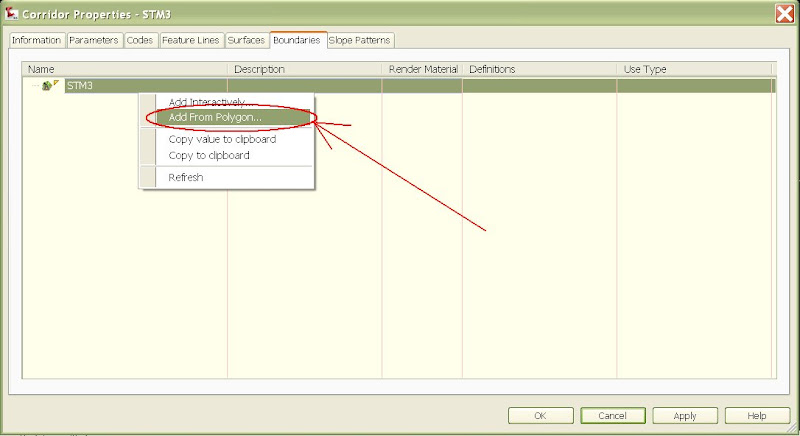
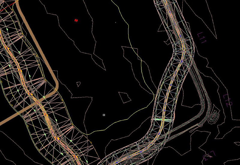
Go to corridor properties, then the boundaries menu. Right click on the surface and select "Add from polygon". Create polylines from your corridor feature lines and join them to form a large closed polyline encompassing your corridor surface. This boundary is static in memory and is NOT updated as you change the original polyline you selected. In fact, you can delete that polyline if you wish and the boundary will remain in memory. The boudary function is a fantastic way of deleting links from a surface tinn by simply excluding them outside of the corridor boundary. The closed polyline boundary is much easier to use than the corridor feature lines (method shown in previous post before this one):
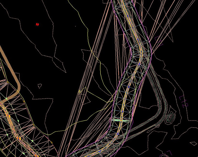
Finished Product:
Tuesday, January 27, 2009
Use Corridor Feature Lines for Surface Boundaries
You can select corridor feature lines for a boundary via the boundary menu in corridor properties. Right click on the surface in the boundary menu to bring up the “add interactively” command. Then tap the start and end of each feature line that you would like to use for the boundary. One caveat to this is that if you have you links overlap around curves, then the feature lines are connected via the stationing order – so you get a overlapping feature line that Civil 3D will not accept as a boundary.
Editing Profile Data via the Panorama Editor
You can enter in the PVI data manually in the panorama editor via the "profile grid view" button on the top right. You can insert PVIs by using the "Insert PVIs-tabular" button redlined above on the left.
Friday, January 23, 2009
$1,000,000 fine levied by Justice Department for Clean Water Act Violations
http://news.findlaw.com/prnewswire/20090107/07jan20091748.html
“WASHINGTON, Jan. 7 /PRNewswire-USNewswire/ -- Five defendants associated with the construction of the Liberty Village housing development in Lynchburg, Va., will pay a $300,000 penalty and fund more than $1 million in stream and wetlands restoration work for alleged violations of the Clean Water Act and permit restrictions during construction, the Justice Department and U.S. Environmental Protection Agency (EPA) announced.
The settlement with Savoy Senior Housing Corporation, Savoy Liberty Village LLC, SDB Construction, Inc., Best G.C., Inc., and Acres of Virginia, Inc., was part of a consent decree lodged today in the Western District of Virginia by the U.S. Department of Justice on behalf of the EPA.”
Map Cleanup and Topology Buffers
When you create a topology buffer for a network topology, map 3D will assign object data to the topology linework you create for said buffer. In order to remove that object data to use this linework for other applications (creating alignments, etc), then you need to delete the topology in order to get the object data to be automatically removed. I had an issue using drawing cleanup and converting arcs to polylines. I could not cleanup the drawing until the linework was no longer associated with a topology.
Thursday, January 22, 2009
Remove Zero Elevation Contours on Corridor Surfaces
Sometimes you can get funky contours because of your corridor alignment/profile targeting and proposed profile accuracy. You can remove this quickly by simply beginning your corridor at one or two from the beginning and end of your target alignment.
Wednesday, January 21, 2009
Group Filters for Easier Layer Managment in Civil 3D
Object and xref layers can get really cumbersome to deal with everytime you use the layer property manager. Use group filters for easy organization and selecting of layers. Using group filters also has the added benefit of reducing the lag time between layer edits you make.
Right click and select New Group Filter:
Drag the desired layers you'd like to use into the group filter you just created:
You're done:
Tuesday, January 20, 2009
Link a Corridor Subassembly to a Feature Line
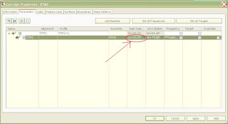
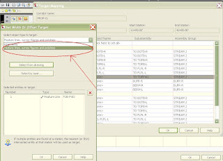
WOW, I stumbled upon a wonderful new feature with 09. You can now link a subassembly target to a feature line for its alignment or profile. The possiblities are endless, but basically, this removes a lot of work creating profiles and will simplify the design process that much more. Using corridor and grading utilites, you can build objects off one another and take advantage of the dynamic property of Civil 3D.
Monday, January 19, 2009
Make alignment text controlled by civil 3D object layer color
Making alignment text color appear byblock requires a couple workarounds to get the display to work out correctly. Currently, the layer the text is set to in the label settings is the layer color that is displayed for the text. In order to get the alignment text object layer to control the color, you will need to make two adjustments – change the text layer to zero, and set the layer color to byblock. The settings you need to adjust are seen in the two screenshots on this post. Changing the text layer to zero forces the alignment text to adopt the properties of the block layer (a basic cad function with blocks).
New 09' Feature Line Select Option
Grading with feature lines has improved with 2009 civil 3D. Right click on any feature line in the prospector to bring up a “select” option. Civil3D will select and zoom to the feature line with this command making it very easy to locate feature lines (especially when compared to 08’).
Saturday, January 17, 2009
Problems deleting bad alignments
Friday, January 16, 2009
Import Garmin Mapsource GPS tracks into AutoCAD & Civil 3D

Make note of the UTM zone for your datum settings in Map 3D. Use the dialog box settings as shown for saving the DXF file. A 3D polyline will be created if the Include elevation information box is checked, otherwise the track will be a normal polyline.
A warning message appears if the track/waypoint information overlays more than one UTM Zone
Now open the DXF file in Map 3D. Make certain that DXF file is selected as the file type.
TR-55 Hydrologic Analysis with Map3D
This is still in draft...
TR-55 Analysis with Map3D
1) Download Soils GIS data
2) Look up hydrologic group data for the GIS soils data
3) Use the soil vlookup function in the CN Database.xls file to facilitate matching of hyd groups to soils types. Will need to set up vlookup table in order to do search.
4) Open the dbf file of the Soils GIS data. This lists the object data for the soils linework that will be imported in to the dwg. Create a column in this file and add the hyd group data. Make certain that the hyd group data matches up to the appropriate soils linework before proceding.
5) Using Map3D, import the shp file you just edited. Adjust the dialog box settings so that the object data and linework comes in correctly. Set the object data template so that the hyd group is included.
6) Prepare the linework for topology creation using map cleanup tools. Create centroids for the linework and be sure to assign a correct block and the appropriate unique layer. The layer assignments are crucial because you will need to do isolation commands with future steps.
7)Another crucial step when creating topologies is that the topology linework must not be altered in anyway, shape, or form after creating the topology. This will affect topology overlays that you will be performing once you prepare all the topologies correctly. I place the linework on its own unique layer and then lock down said layer.
8)Create an annotative template for the soils topology. This is a little tricky at first, but incredibly easy to master after a couple go arounds. The template will be attached to the centroids of the topologys whose attributes you want annotated.
8)Now that the soils linework has been taken care of, and transformed into a map3d topology.
9)Create linework for the watersheds in the drawing. Make sure that the linework of each watershed consists of line segments only. Polygons will only be assigned to linework that forms a closed polygon, and an error message will be returned for errant linework that doesn’t form a closed polygon.
10) When creating the topology from the watershed linework, make certain to have MAP3D create centroids when the topology is formed (AND assign them to a unique layer). Define the object data table for the watershed topology with the watershed name. Assign the object data tables to the centroids just created.
11) Manually enter in the watershed names for the watershed topology.
12) Delineate the various land uses according the cover types listed in USDA Technical Release 55 - Urban Hydrology for Small Watersheds, pgs (2-5)-(2-8). Create the linework in a simlar fashion to how it was done in the soils and watershed topologys .
13) Create centroids for the linework when creating the landuse topology. Create variables in the object data template for land use and condition and centroid id. Assign the object data template for land use to the pertinent centroids.
14) Export the land use topology to an ESRI shp file. A database file (.dbf) is created along with the shp file for storing the object data. This table can be opened and edited in either excel or access. The centroid id that was assigned for the land use object data table will become the go between for transferring data.
15) Use the excel pulldown lists for selecting the land uses and condition. Not doing so jeopardizes automated steps futher ahead because the land use nomenclature might not match up to its database lookup location.
16 )Arrange the data columns so that a copy and paste operation can be performed that will transfer the centroid id, land use, and condition between the excel worksheet and the dbf file.
17) Transfer the data from the land use and condition back to the dbf.
18) Reimport the just edited shp file. (try…. Delete the line work from the previous topology prior to importing the shp file with updated database)
-----------------------------------------------------------------------
> Overlay the topologies
> Create object data tables for the overlay topology with attributes of each overlay (and the curve number (CN) and area for the final overlay)
> For final topology, export the topology to a shp file. Go into the the dbf and grab the centroid id, land use, condition, and hydrologic group and copy to the CN Lookup tab of the CN database excel spreadsheet. Make certain that all columns line up correctly and the vlookup function of column A will automatically assign a curve number for each centroid. Copy this data back to the CN column so that each centroid id has been assigned a curve number.
> in order to assign annotate the attributes of the final topology, the exported shp file will need to be reimported into the drawing.
Natural Channel Design via Corridor Modeling
The corridor model works well in stream restoration design. By using a combination of alignments and profiles in conjunction with assemblies and sub-assemblies, a tin surface is quite easily made and edited.
The model being described uses three profiles input by the user – thalweg, toe, and bankfull. Alignments are made for each geometry point in order to specify the locations of the subassemblies that build each feature of the natural channel.
Below is shown a typical plan view of the alignments associated with a stream channel:
There are three cross sections used in building the corridor. One is the riffle, the other two are meander pool cross sections that are mirrors of one another.
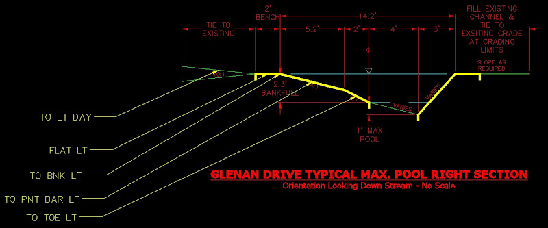
Shown below is the riffle detail cross section:
The schematic geometry above is labeled with the corresponding subassembly used for building the corridor surface. The subassemblys use the link width an slope assembly found in the imperial generic tool palette. This link can be set to grade for a set length and slope. The beauty of this subassembly, however, lies in the ability of the user to override the width and slope preference with an alignment or profile, respectively. Either/or the profile and alignment can be used. Before this post gets into the process of the assembly contruction, we will shortcut to where the targets get set for the subassemblies within the assembly.
Under the corridor properties, go under the parameters tab and go to the "Set All Targets" tag in the top right hand corner:
Target Mapping:
Shown are the subassemblies constructed to form the entities of the assembly:
Thursday, January 15, 2009
Civil3D Object Color Control
You can override layer color assignments using the plot style control toolbar and the color control pulldown menu. To return the color to normal set the layer to bylayer. The layer has to be adjusted in the style as byblock, otherwise this trick will not work.
Friday, January 9, 2009
Data Extraction Command
The export block attributes express tool is great for exporting MAP 3D attributes to excel for editing. Recently, I discovered a great way to input information into attribute blocks with a pull down table. This helps ensure that nomenclature is perfect for a database lookup down the road. Unfortunately, this data is not considered a annotation attribute and is not exported when using the express tool mentioned above. The command, dataextraction, is a more comprehensive (but not as quick and easy) export command that will let you tailor the output exactly as you want it formatted. Using the exported information from the dataextraction command, you can copy and paste it to the object data table of pertinent topology.
Wednesday, January 7, 2009
Visibility Function on Dynamic Blocks
The block authoring palettes that were first included with AutoCAD 2006 have some very useful dynamic features. Among them is the visibility feature. With this command, you can create a pull down menu in your properties dialog box that will control the visibility of components of a block. The current visibility displayed can also be exported via an attribute block. This is a useful tool for quickly entering in attribute data via a quick pull down menu.
Tuesday, January 6, 2009
Panorama Editor
The panorama editor is used for manually entering/editing profiles, feature lines, alignments, etc. To make it visibile, there is a button for visibility at the top of the Tool Prospector.
Monday, January 5, 2009
Using Profiles to Import Elevations
I recently had a dilemma where I was given distances along a line with corresponding elevations and asked to create 3d polylines from them. In order to avoid the difficulty of manually importing the points, the process can be automated with ease. Creating a vertical profile allows you to enter tab delineated information. By using this feature in conjunction with a simple corridor – it is possible to create a proposed profile. Using the proposed profile in conjunction with a simple corridor setup, you can extract a feature line from the simple corridor with grips set at the distances and elevations you import from a space delimited text file.
Blog Archive
-
▼
2009
(23)
-
►
January
(21)
- Revert the Layer Properties Manager Back to Static...
- Use Static Polylines for Corridor Boundaries
- Use Corridor Feature Lines for Surface Boundaries
- Editing Profile Data via the Panorama Editor
- $1,000,000 fine levied by Justice Department for C...
- Map Cleanup and Topology Buffers
- Remove Zero Elevation Contours on Corridor Surfaces
- Group Filters for Easier Layer Managment in Civil 3D
- Link a Corridor Subassembly to a Feature Line
- Make alignment text controlled by civil 3D object ...
- New 09' Feature Line Select Option
- Problems deleting bad alignments
- Import Garmin Mapsource GPS tracks into AutoCAD & ...
- TR-55 Hydrologic Analysis with Map3D
- Natural Channel Design via Corridor Modeling
- Civil3D Object Color Control
- Data Extraction Command
- Visibility Function on Dynamic Blocks
- Purge Command
- Panorama Editor
- Using Profiles to Import Elevations
-
►
January
(21)


