The corridor model works well in stream restoration design. By using a combination of alignments and profiles in conjunction with assemblies and sub-assemblies, a tin surface is quite easily made and edited.
The model being described uses three profiles input by the user – thalweg, toe, and bankfull. Alignments are made for each geometry point in order to specify the locations of the subassemblies that build each feature of the natural channel.
Below is shown a typical plan view of the alignments associated with a stream channel:
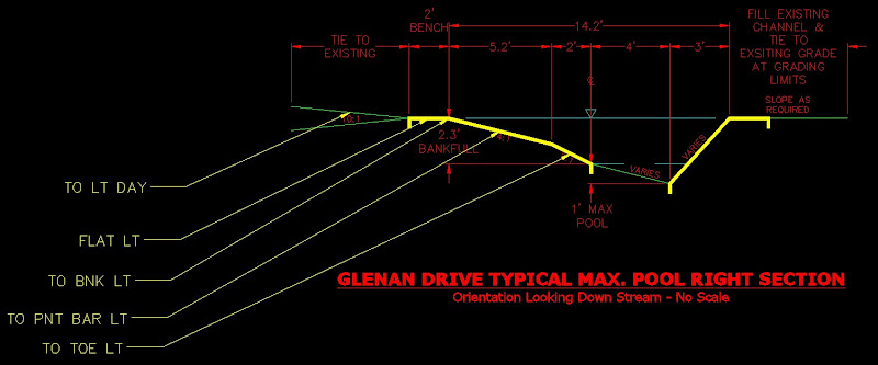
There are three cross sections used in building the corridor. One is the riffle, the other two are meander pool cross sections that are mirrors of one another.

Shown below is the riffle detail cross section:
The schematic geometry above is labeled with the corresponding subassembly used for building the corridor surface. The subassemblys use the link width an slope assembly found in the imperial generic tool palette. This link can be set to grade for a set length and slope. The beauty of this subassembly, however, lies in the ability of the user to override the width and slope preference with an alignment or profile, respectively. Either/or the profile and alignment can be used. Before this post gets into the process of the assembly contruction, we will shortcut to where the targets get set for the subassemblies within the assembly.
Under the corridor properties, go under the parameters tab and go to the "Set All Targets" tag in the top right hand corner:
Target Mapping:
Shown are the subassemblies constructed to form the entities of the assembly:


